


Physical interfaces and their security issues

A high percentage of devices developed for the industrial world have physical interfaces that allow secondary communications to be established. These communications allow the execution of important tasks such as the management of the devices themselves or the modification of the way they interact with industrial processes. Although in order to use these interfaces, in most cases it is necessary to have physical access to the device, manipulation of the device through these interfaces allows attackers to manipulate the operation of the system without leaving any trace if there are no mechanisms to protect the asset from hardware hacking.
When talking about interfaces, generally, input and output interfaces that handle large amounts of data are mentioned, but there are also low-speed physical interfaces that are mainly found in microcontrollers and devices, which do not require high bandwidth. Among these interfaces, two types can be distinguished:
- Serial. Transmit a single bit per clock cycle.
- Parallel. Transmit multiple bits per clock cycle.
A clock cycle is the amount of time between two pulses of an oscillator. In general, the greater the number of pulses per second, the faster the information can be processed.
There are multiple physical interfaces, but in this article, the main ones will be detailed: UART, SPI, I2C and JTAG.
UART
A UART (Universal Asynchronous Receiver/Transmitter) is a block of circuitry responsible for implementing serial communication, acting as an intermediary between parallel and serial interfaces. At one end of the UART is a bus of eight or more data lines (plus some control pins), while at the other are the two serial wires: RX and TX.
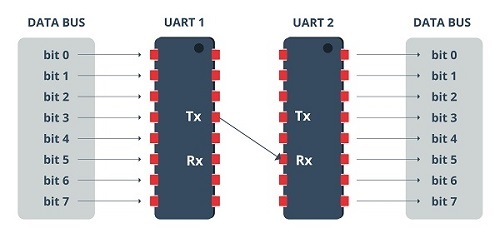
- UART. Source -
UARTs exist as stand-alone integrated circuits, but are more commonly found inside microcontrollers, which may even contain multiple UARTs. As indicated by the R and T in the acronym, they are responsible for sending and receiving serial data.
- On the transmission side, you must create the data packet, adding synchronisation and parity bits, and send that packet over the transmission line with a synchronisation.
- On the receive side, it must sample the RX line at a rate according to the expected baud rate (number of signal units per second), collect the synchronisation bits and display the data.
More advanced UARTs can send the received data to a buffer, where it can remain until it is requested by the microcontroller. These usually make use of the first-in-first-out (FIFO) principle and can range in size from a few bits to thousands of bytes.
In cases where the microcontroller does not contain any UARTs, they are implemented in software, so that the interface can be bit-modified and controlled directly by the processor.
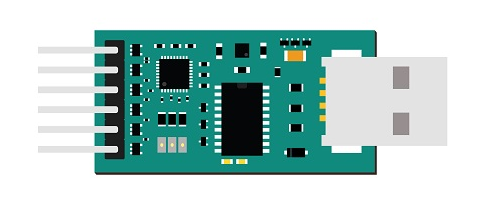
- USB to UART board. Source -
SPI
The SPI (Serial Peripheral Interface) is a synchronous serial data protocol interface, developed by Motorola, which acts as an interface bus, operating in full-duplex and where data can be sent and received simultaneously.
SPI can operate at faster data rates than other peripherals such as UART and I2C, this speed can be as high as 8Mbits or more. This advantage is because this type of interface transfers data without interruption, as it is a stream of bits that are being sent and received continuously.
To keep the master and slave (peripheral device) in sync, SPI uses separate lines for the data, plus a shared clock that functions as an oscillating signal that tells the receiver when to sample the bits on the data line.
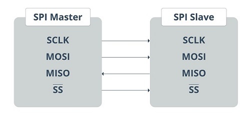
- SPI Master and slave. Source -
The transmission of data bits takes place every clock cycle, which means that the data transfer rate is determined by the frequency of the clock signal generated by the master. This data is transmitted bit by bit.
When the receiving slave detects the clock signal, it prepares to read the data bits on the data line. SPI is used in places where speed is important, such as flash memory (e.g. SD cards), display modules, places where information is rapidly updated and changed (e.g. sensors, thermometers), real-time clocks (RTC), analogue-to-digital converters, etc.
I2C
I2C (Inter-Integrated Circuits) combines the best features of SPI and UART in that you can connect multiple slaves to a single master (like SPI) and you can have multiple masters controlling one or more slaves. This is useful when you want to have more than one microcontroller recording data on a single memory card or displaying text on a single LCD.
Like UART communication, I2C only uses two wires to transmit data between devices:
- SDA (Serial Data). The line for the master and slave to send and receive data.
- SCL (Serial Clock). The line carrying the clock signal.
I2C is a serial communication protocol, so data is transferred bit by bit over a single cable (the SDA line) and, like SPI, I2C is synchronous, so bit output is synchronised with bit sampling by a shared clock signal between the master and slave, which is always controlled by the master.
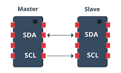
- I2C master and slave. Source -
I2C communication is considered slightly more complex than SPI and UART communication. Initially, the message being transmitted is divided into two types of frames: an address frame, and one or more data frames. The address frame is where the master tells the slave where the data is being sent. There can be more than one data frame consisting of eight-bit data passing from the master to the slave. After the clock line goes low, data is placed on the data line. This data is sampled after the SCL goes high. When the master device stops using SCL high and starts using SDA low, it wants to indicate to the slave devices that transmission is about to begin. If there is more than one master device to start communication at a time, the device that is the first to use SDA low will take control of the buses first.
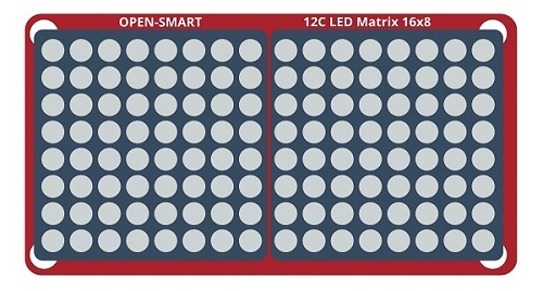
- I2C Display module. Source -
JTAG
JTAG (Joint Test Action Group) is essentially a standard that is used for the verification, testing and scanning of PCBs (Printed Circuit Boards) after manufacturing. It is an interface that provides a channel to communicate and control the circuit board chips of a given piece of hardware. This interface also allows real-time debugging by allowing to directly take control of the clock cycles through the software.
JTAG was introduced in the 1980s, in order to make the PCB testing relatively easier and more complete. Since then, the JTAG interface has been used for all sorts of purposes, such as programming, debugging and testing. It connects to an on-chip test access port, or TAP, through which it gains access to a set of test registers, which present the logic levels of the chip and the capabilities of the device under test.
One of the applications where JTAG is very useful is in boundary scanning, where it allows testing of the interconnections present between the various ICs or chips on the board without having to obtain or use a physical test probe. The main advantage of this scan is that it is not necessary to physically access the pins, but the values can be read and analysed as required.
Example of attack via physical interfaces
The physical interfaces mentioned above are increasingly being implemented in industrial environments, this type of interface has many benefits, but also has the disadvantage that they are not sufficiently secure.
Due to the low security of these interfaces, different techniques and technologies have been created that can produce cyber-attacks capable of causing major problems to these interfaces.
For example, one of these technologies is the BusPirate, a microcontroller capable of communicating with protocols such as UART, SPI, I2C and JTAG via the USB interface, making cyber-attacks easy to carry out.
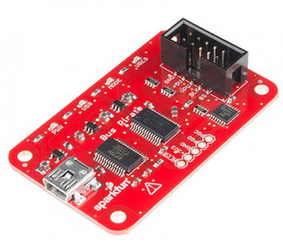
- Bus pirate. Source -
Countermeasures and conclusions
However, securing interfaces is not an easy task, especially if they are physically accessed. The most effective way to protect them is by using other physical boards that act as an intermediate layer between the interfaces and the device. These boards contain an FTDI chip through which they can communicate via the most used protocols and thus be able to interpret and analyse all the traffic.
If these security boards are not available, measures can be implemented by software. This option works particularly well for IoT devices, but is less effective for embedded devices, so this option is only recommended if it is not possible to install a physical security device such as the above-mentioned plates.
In short, physical interfaces often go unnoticed and are given a low priority when it comes to establishing cybersecurity measures in most infrastructures, and the reality is that they are a very powerful tool through which an attacker could carry out many operations that would put both the confidentiality of the company or even the physical safety of workers at risk.


